Introduction
Two of the three currently existing working CD-i emulators use Low-Level Emulation or LLE: they emulate the hardware of a specific CD-i player and then run the original system ROM software for that player on it.
For CD-i emulation there is, however, another possible approach, due to the fact that the CD-i system functional specification (the so-called Green Book, sometimes abbreviated FFGB) is essentially a software API standard not unlike e.g. the Win32 API: it does not directly specify any CD-i hardware except for “a 16-bit data bus version of the 68000 family of microprocessors” (FFGB VIII.8 System Resources and Performance, section 8.2 MPU).
Of course, the Green Book strongly suggests hardware capable of decoding a number of specific disc, audio, image and video formats. But it does not specify the layout or sometimes even existence of any control registers, memory locations or other hardware features to control that decoding; instead, system calls are provided for this.
This makes it possible to implement the Green Book completely in software (High-Level Emulation or HLE) without any use of existing CD-i system ROM software, thus neatly sidestepping any copyright or other issues with using the original ROMs. I have discussed the potential advantages and disadvantages of this approach elsewhere but for now let’s take the HLE approach as given.
There are now at least four existing attempts at High-Level Emulation of CD-i players:
- Pete Dabbs’ CD-iCE emulator (never fully released), http://cdice.emuhq.com (on archive.org)
- CD-i Fan’s CD-i Emulator “os9emu” feature (unreleased), https://www.cdiemu.org
- Stovent's CeDImu "SoftCDI" branch, https://github.com/Stovent/CeDImu/tree/softcdi
- techmetx11’s KiwiCDi emulator, https://codeberg.org/KiwiCDi/kiwicdi
This blog post discusses a part of the CD-i system that contains a number of (mostly undocumented) algorithms that HLE attempts must be aware of in order to arrive at a working emulation for actual released CD-i titles: the display control tables collectively known as the Display Control Program or DCP.
Green Book specification
The CD-i video display system consists of a number of video planes that are shown in a specific front-to-back order; for each position on the screen the color visible is taken from the front-most non-transparent plane. In a base case CD-i player there are four such planes: the cursor plane, graphics plane A, graphics plane B and the background/external video plane.
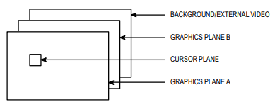
The A and B planes are completely programmable on a per-line basis (including their image formats, transparency and relative Z-order), the other planes are more restricted (the cursor plane shows at most a single 16x16 pixel single-color cursor shape, and the background plane shows a single solid color). If Digital Video functionality is present in the CD-i system, the background plane can (again on a per-line basis) be made to show external video (a window on an MPEG video stream surrounded by (another) solid background color). Each programmable plane can only read from a specific area (bank) of memory, allowing them to be decoded in parallel.
Almost all control of the video planes is implemented via the Display Control Program or DCP, which is a set of control instructions that are executed in the vertical retrace period (the Field Control Tables, or FCTs) or the horizontal retrace period (the Line Control Tables, or LCTs). Planes A and B both have their own set of FCT and LCT tables whose instructions mostly control their own plane although there are some exceptions. For each plane, one FCT and multiple LCTs can be linked together in such a way as to provide at most 1024 application DCP instructions to be executed before each video field and up to 8 DCP instructions to be executed before each active video line.
The Green Book specifies the detailed bit layouts of each DCP instruction, and the application can basically put them into the FCTs and LCTs almost any way it chooses, subject to some restrictions specified in the Green Book and various Technical Notes. In particular, the instructions controlling the linking and execution of the tables must be put into place using system calls, although there are some applications that violate this restriction (see below).
The Green Book specifies DCP instructions Load control table line start pointer ($20) and Load display line start pointer ($40) for specifying memory addresses, although it does not allow applications to use the former directly (see the restrictions specified above).
Player hardware implementations
There exist two basic hardware implementations of the CD-i video system, characterized by the chipset used. The initial players used two Philips SCC66470 Video and System Controller (VSC) chips, one per plane, that fed their output to a final Video Synthesizer chip (versions called VSR and VSD exist but they are functionally compatible). Some non-Philips players replace the two VSC chips with a single Sony CXD8297AQ Dual Video and System Controller (Dual VSC) chip but still use a separate Video Synthesizer chip. Later players switched to a single chip implementation, the Motorola MCD212 Video Display and System Decoder (VDSC) chip that combines all three of the initial chips.
The implementations are almost 100% compatible in their implementation of the Display Control Program but differ in their control registers and memory locations (which are not specified in the Green Book). Both implementation variants actually start the DCP for each plane at the same fixed address offset into their respective memory banks, but the start addresses of the memory banks differ. For the VSC implementations, the banks start at address zero (0x0) for plane A and 512 KB (0x80000) for plane B while for the VDSC the second bank starts at 2 MB (0x200000). This has been the source of some compatibility problems for CD-i titles that assume these addresses (strictly not allowed by the Green Book but nevertheless a fact of life for actual released CD-i titles).
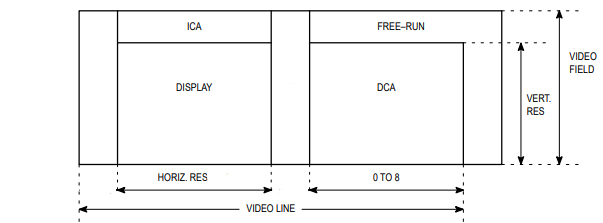
There is also a difference in the conceptual model of the DCP between the hardware implementations and the Green Book, causing a host of complications. To avoid confusion, we will refer to the hardware table implementing the FCT functionality as the Image Control Area or ICA, and the table implementing the LCT functionality as the Display Control Area or DCA; these terms are taken from the Philips SCC66470 and Motorola MCD212 chip documentation.
Whereas the Green Book specifies the instructions of each LCT line as to be executed *before* each video line, the hardware actually executes a DCA line *after* each video line. To implement the Green Book model the CD-i video driver maintains an ICA for each plane (called the “shadow FCT” in the Green Book) that contains the instructions of the linked LCT line after those from the application FCT. It also includes some additional instructions (e.g. for the cursor plane) in the ICA that are not specified in the Green Book.
The hardware ICA/DCA implementation for each plane uses two registers known as the Video Start Register (VSR) and the DCA Pointer (DCP). Both ICA instructions and graphic pixel data are fetched using the VSR register, which necessitates reloading the register at the end of the ICA.
There are five DCP instructions to reload each of these registers and/or stop the processing of instructions until the next line or field: STOP ($00), RELOAD DCP ($20), RELOAD DCP AND STOP ($30), RELOAD VSR ($40), RELOAD VSR AND STOP ($50).
Only two of these instruction codes are specified in the Green Book, and their specification differs somewhat from the hardware. In particular, the Green Book allows the $40 instruction to be used in both FCT and LCT, but the hardware implementation does not directly support that in the ICA and consequently some special processing is needed in the video driver. The hardware also needs STOP instructions (one of $00, $30, $50) at the end of the DCA and ICA; these are not specified in the Green Book.
You can find most hardware details in the following datasheets:
Philips SCC66470 Video and System Controller
http://www.icdia.co.uk/docs/scc66470.pdf
VSR Functional Specification (preliminary version, July 1986)
https://www.cdiemu.org/download/vsr-functional-specification.pdf
Motorola MCD212 Video Decoder and System Controller
http://www.icdia.co.uk/docs/mcd212rev0.pdf
Note: The Pixel Accelerator (PIXAC) functionality of the original VSC chips is not used by any of the CD-i system ROMs nor standardized in the Green Book and was not carried forward into the VDSC chip.
Software techniques and compatibility
Many CD-i titles use a technique called “direct LCT writing” where they directly (e.g. without using the system calls provided for that purpose) modify the LCT tables in memory, therefore forcing the memory structure of these tables even for a HLE implementation of the video system. There are various ways to get the memory addresses of these tables, varying from
a) an “almost green” approach exploiting some properties of the system calls and tables,
b) reading the (undocumented but unvarying) device driver variables to find the tables, and
c) following the actual DCP in memory starting at the hardware-implemented start addresses.
Approach a) was described by me in The Interactive Engineer, Volume 5, No. 4, July/August 1996, http://icdia.co.uk/iengineer/IE_9604.pdf, in an article called Direct Line Control Table Access; this was an attempt to get the information out “into the open” that was being used by many CD-i developers as learned from private conversations.
Approaches b) and c) can also be used to perform “direct FCT writing” but then you need to modify the “shadow FCT” which introduces additional problems; nevertheless, I think there are released CD-i titles out there that use these approaches.
The use of these approaches requires a mostly hardware-equivalent HLE implementation of the video system and if you want to support approach b) you even need some amount of device driver variable compatibility.
The rest of this document is an attempt at describing the algorithms used by the CD-i video driver to implement the Green Book model of the DCP using the ICA/DCA model provided by the hardware, so that compatibility between HLE implementations and the CD-i titles exploiting (part of) these algorithms can be maintained.
Caveat: I have constructed these algorithms from a limited amount of reverse engineering; there may be some fine details not covered below.
Display Control Program algorithms
The CD-i video driver allocates additional memory beyond the user-accessible area for each FCT and LCT, from Green Book section VIII.7.5.2.2.4 FCTs and LCTs:
When creating an LCT, the driver will take the number of lines requested, add two lines, divide by 2 for normal resolution, and then multiply by 64 bytes per line.
For FCTs, the driver will allocate a block for the number of instructions specified (plus one for the link instruction) times 4 bytes per instruction. If resolution is specified as high resolution, then this number is doubled.
The Green Book also briefly mentions the shadow FCT in the same section:
Additionally, when the application executes DC_Exec, a shadow FCT is allocated and the contents of the user's FCT is copied into the shadow FCT. The shadow FCT is larger than the user FCT by 10 instructions (40 bytes) for normal resolution and 20 instructions (80 bytes) for high resolution. This is to accommodate the first line of the LCT linked to by the FCT and some extra instructions to accommodate some features of the hardware.
The actual ICA seen by the hardware is larger, because it also includes instructions for loading the cursor plane (only for plane A) and linking various ICA parts together. The cursor instructions are not specified in the Green Book which instead specifies various Graphics Cursor (GC) API calls in section VII.2.3.4.2 Graphics Cursor Functions.
For easier discussion, let’s assign symbolic names to some DCP control instructions, both the Green Book versions and the hardware ones:
/* DCP operation codes from the Green Book */
#define OP_CADR 0x20 /* Load control table line start pointer, FFGB V.4.5.1 */
#define OP_DADR 0x40 /* Load display start address, FFGB V.4.5.1 */
/* DCP operation codes from the hardware documentation */
#define DCP_STOP 0x00 /* Stop processing, MCD212 5.4.4 */
#define DCP_DCR 0x20 /* Reload DCP register, MCD212 5.4.4 */
#define DCP_DCR_STOP 0x30 /* Reload DCP register and stop, MCD212 5.4.4 */
#define DCP_VSR 0x40 /* Reload VSR register, MCD212 5.4.4 */
#define DCP_VSR_STOP 0x50 /* Reload VSR register and stop, MCD212 5.4.4 */
#define DCP_CPOS 0xCD /* Load Cursor Position register, MCD212 5.4.4.9 */
#define DCP_CCTL 0xCE /* Load Cursor Control register, MCD212 5.4.4.10 */
#define DCP_CPAT 0xCF /* Load Cursor Pattern register, MCD212 5.4.4.11 */
In order for the DCA/ICA structures to be a faithful Green Book FCT/LCT implementation the ICA for each plane must:
1) contain a DCP_DCR to tell the hardware where to start reading DCA instructions
2) end with a DCP_VSR_STOP to tell the hardware where to start reading graphics pixels
3) not contain any other DCP_VSR or DCP_VSR_STOP to avoid disrupting ICA processing
4) not contain any DCP_STOP or DCP_DCR_STOP to avoid disrupting ICA processing
5) contain the contents of the application FCT
6) contain the contents of the linked line of the LCT linked from the FCT
7) point the DCP_DCR (see 1) at the next line of the LCT linked from the FCT
The DCA for each plane then starts at that second line of the LCT linked to from the FCT.
Note: The Green Book does not allow linking to an LCT from a line linked from the FCT.
In plane A the ICA must also contain the DCP_CPOS, DCP_CCTL and DCP_CPAT (16x) instructions.
ICA execution starts at either offset 0x400 (non-interlaced or odd interlaced fields) or 0x404 (even interlaced fields) in each plane; those need to contain DCP_VSR instructions.
System initialization
At system initialization time, the boot code initializes a simple ICA and a single-line DCA for each plane at offset 0x408 that just displays a constant background color. Here’s an (edited) DCP trace from CD-i Emulator (“et dcp”) running a CDI 605 system ROM:
Driver initialization
When the CD-i video driver initializes itself during its Init call, it allocates cursor pattern memory and inserts this in front of the existing ICA for plane A:
The driver stores the address of the cursor DCP at offset V_CurDCP of the driver static storage:
//* Cursor Instructions DCP.
V_CurDCP = 0x010E,
The existence of the cursor DCP means that DCP instruction execution from the application FCT and linked LCT line is not synchronized between planes; CD-i applications must take care to account for this. Instruction execution from the remaining LCT lines is synchronized between planes, with plane A instructions taking precedence over plane B instructions.
The driver stores the identifiers for various FCTs at the following driver static storage offsets:
//* Identifier for original plane A FCT (allocated by Init).
V_Orig1 = 0x00D2,
//* Identifier for original plane B FCT (allocated by Init).
V_Orig2 = 0x00D4,
//* Identifier for shadow plane A FCT (allocated by DC_Exec).
V_Shdw1 = 0x00D6,
//* Identifier for shadow plane B FCT (allocated by DC_Exec).
V_Shdw2 = 0x00D8,
//* Identifier for current plane A FCT (set by DC_Exec).
V_Curr1 = 0x00DA,
//* Identifier for current plane B FCT (set by DC_Exec).
V_Curr2 = 0x00DC,
//* Identifier for active plane A FCT (original or shadow, set by DC_Exec).
V_Actv1 = 0x00DE,
//* Identifier for active plane B FCT (original or shadow, set by DC_Exec).
V_Actv2 = 0x00E0,
Note: The names of all static storage offsets are my own invention.
The original plane A/B FCTs are given identifiers 1 and 2 (stored into V_Orig1/2) and initialized to correspond to the boot ICAs at offset 0x408; this way a DC_Exec can internally substitute one of these FCTs if the corresponding application-specified FCT identifier is zero.
The variables V_Activ1/2 are then set equal to V_Orig1/2.
The driver initialization also creates an event named line_event and stores the identifier at the following static storage offset:
//* Identifier for "line_event", allocated by Ev_Creat.
V_LineEvt = 0x00EE,
DC_Exec implementation
When a DC_Exec system call is executed to activate application-created FCTs, it prepares a new shadow FCT for each changed FCT (i.e., where the new id differs from the V_Curr1/2 value), initializes it from the application-created FCT (see below) and then activates it by replacing the DCP_VSR instruction at the end of the cursor DCP (for plane A) or offset 0x400 (for plane B). The V_Shdw1/2, V_Curr1/2 and V_Actv1/2 variables are updated with the identifiers of the new shadow, current and active FCTs. The old shadow FCTs are then deallocated.
The update itself is not synchronized to the video scan in any way, but deallocation of the old shadow FCTs is delayed for two field periods so that it is no longer used. This causes the DC_Exec call to be relatively slow (several milliseconds).
All the FCT and LCT memory allocation is done from the appropriate memory bank by using the F$SRqCMem system call with a memory color parameter of either VIDEO1 (0x80) or VIDEO2 (0x81).
Shadow FCT implementation
As described in the Green Book, the shadow FCT is larger than the application FCT by 10 instructions, of which 8 are used to contain the instructions from the linked LCT line. The last two are used for the DCP_DCR and DCP_VSR_STOP instructions that tell the hardware where to find the DCA and where to start fetching pixel data (the shadow FCT is always the last part of the ICA; for plane A it is preceded by the cursor DCP).
Since the VSR is used for ICA scanning, any OP_DADR instruction in the application FCT and linked LCT line must be replaced (typically with a DCP_NOP) and the address moved to the DCP_VSR_STOP instruction at the end of the shadow FCT.
Technically the same holds for OP_CADR instructions but since these are not allowed to be written except by the DC_FLnk and DC_LLnk system calls there is no need to perform any instruction replacements.
DC_FLnk implementation
This system call writes an OP_CADR (DCP_DCR) link instruction at the end of the application FCT in the space allocated for it. However, if this FCT is also currently executing, the corresponding shadow FCT needs to be updated as well
To update the shadow FCT, the 8 instructions of the linked LCT line are copied into the shadow FCT (while performing the OP_DADR replacement algorithm specified above) and the DCP_DCR at the end of the shadow FCT is then updated to point to the next line.
DC_LLnk implementation
This system call writes an OP_CADR (DCP_DCR) at column 7 of the specified LCT line, replacing any instruction that is already there. However, if this LCT line is linked from a currently executing FCT, the corresponding shadow FCT needs to be updated as well.
To update the shadow FCT, the DCP_DCR instruction at its end must be updated to point to the linked LCT line.
DC_WrFCT and DC_WrFI implementation
These system calls write instructions to an application FCT. If this FCT is also currently executing, the corresponding shadow FCT must be updated as well while performing OP_DADR replacement as described above.
DC_WrLCT, DC_PWrLCT, DC_WrLI and DC_NOP implementation
These system calls write instructions to an LCT. If they write into a line that is linked from a currently executing FCT, the corresponding shadow FCT needs to be updated as well by copying the instructions into it while performing OP_DADR replacement as described above.
DC_RdFCT, DC_RdLI, DC_RdLCT, DC_PRdLCT implementation
These system calls read instructions from application FCTs and LCTs. No special processing is needed as shadow FCT modifications are never necessary.
Implementation of other Display Control system calls
The other DC system calls are relatively straightforward, they allocate and release identifiers and memory as needed (DC_CrFCT/DC_CrLCT and DC_DlFCT/DC_DlLCT), set interrupt handling variables (DC_SSig/DC_Relea) and set hardware register bits (DC_SetCmp, DC_Intl and DC_SetAR).
Activation of interlace mode will cause the ICA start address to alternate between offsets 0x400 and 0x404 in each plane; this introduces additional complexity into most of the algorithms described above that I have not explored.
Implementation of video interrupt processing
If the application puts the DCP instruction Signal when scan reaches this line ($60) at any position in the DCP, it will trigger a video interrupt when that instruction is executed (which can be multiple times in a single video field scan). During that interrupt, the OS-9 signal specified by the last DC_SSig system call must be sent to the calling process as if by the F$Send system call and the line_event event must be pulsed as if by the F$Event system call with d1.w=$8009 (Ev$Pulse activating all processes) and d2.w=1 (event pulse value); these system calls are made from system state.
Some applications intercept these calls by modifying the relevant system call dispatch tables, either directly or by using the F$SSvc system call specifically provided for that purpose; this allows them to insert code into the actual video interrupt routine.
This technique is described in TechNote #089 A New Method for Video Scan Synchronization in CD-i, http://icdia.co.uk/notes/technote089.pdf and referenced in several other TechNotes; it is therefore fully sanctioned and used by many applications but relatively cumbersome to implement in an HLE implementation.
Implementation of Graphics Cursor system calls
The various GC system calls all write information into the cursor DCP but are otherwise relatively straightforward. The GC_Org and/or GC_Pos system calls probably modify driver variables as well but I have not explored this.
Implementation of ID tables
For keeping track of FCT and LCT identifiers the driver utilizes so-called ID tables; these are described in FFGB VIII.7.5.2.2.1 for UCM which references back to FFGB VIII.7.5.1.3 for CDFM. The ID table header addresses for the video driver are stored at the following static storage offsets:
//* ID table for regions.
V_RgnIDT = 0x00FA,
//* ID table for fonts.
V_FntIDT = 0x00FE,
//* ID table for FCTs.
V_FctIDT = 0x0102,
//* ID table for LCTs.
V_LctIDT = 0x0106,
//* ID table for drawmaps.
V_DmpIDT = 0x010A,
Here is a declaration for the ID tables:
/** ID table implementation.
*
* ID tables are described in FFGB VIII.7.5.1.3 (CDFM) and VIII.7.5.2.2.1 (UCM).
*
* Although ID at first appears to be an abbreviation of IDentifier,
* it is better understood as shorthand for Information Descriptor.
*
* Each ID table entry contains the address, size, memory color and
* some flags for a CDFM soundmap descriptor or an UCM region, font,
* FCT, LCT or drawmap descriptor. Each of these has its own format,
* described in separate FFGB parts, but they are allocated and managed
* with the common ID table data structure.
*/
BEGIN_DATA_TYPE(Os9IdTable, "ID table")
DATA_FIELD(0, W, IDT_Alloc, "Number of allocated IDs")
DATA_FIELD(4, L, IDT_AllocSize, "Allocated size of table")
DATA_SIZE(16, IDT_SIZE, "Size of ID table header")
END_DATA_TYPE()
BEGIN_DATA_TYPE(Os9IdTableEntry, "ID table entry")
DATA_FIELD(0, VP, ID_Addr, "Address of descriptor memory")
DATA_FIELD(4, L, ID_Size, "Size of descriptor memory")
DATA_FIELD(8, B, ID_Color, "Color of descriptor memory")
DATA_FIELD(12, W, ID_Flags, "Flags for descriptor")
DATA_SIZE(16, ID_SIZE, "Size of ID table entry")
END_DATA_TYPE()
Each field is described by a DATA_FIELD macro as follows:
DATA_FIELD(byte_offset, data_type, field_name, field_decription)
where data_type VP means Virtual Pointer and B/W/L are Byte/Word/Long, respectively.
All ID table memory allocation is done with the F$SRqMem system call and is thus not memory bank specific. Descriptor memory, however, is allocated with F$SRqCMem using the ID_Color value.
The original FCTs are given ID_Addr values corresponding to offset 0x408 in their respective memory banks and ID_Size values of 0xF8, with ID_Color being either VIDEO1 or VIDEO2.
I have not explored the usage of ID_Flags for FCT and LCT table entries.
Applications using approach b) as specified in the section Software techniques and compatibility above will read the ID tables for FCTs and/or LCTs.
No comments:
Post a Comment